
Onions in Your Plant
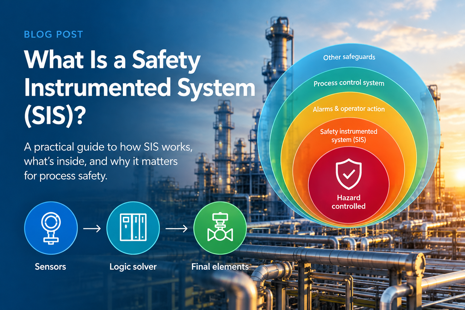
If you have ever attended process safety training, you have probably seen the “Onion” model.
It shows how different protective systems can be arranged as concentric layers around a hazardous process. These are known as Layers of Protection (LOPs), and each layer is intended to help prevent a hazardous event from developing into an accident.
For these layers to provide effective risk reduction, they need to be sufficiently independent. In other words, one layer should be capable of performing its protective function even if another layer fails.
One particularly important layer is the Safety Instrumented System (SIS).
An SIS is an automatic system designed to detect hazardous or abnormal conditions and take the process to a safe state, helping prevent an accident or reduce its consequences.
So, what exactly is an SIS—and what makes it different from an ordinary process control system?
What Does a Safety Instrumented System Do?
Depending on the application, a safety instrumented function can operate in different modes.
Demand Mode
In many process industry applications, the SIS remains ready to act and intervenes when a specific dangerous condition occurs.
For example:
High pressure detected → SIS initiates shutdown → Shutdown valve closes → Process moves toward a safe state
This is known as a demand mode safety function.
The SIS is not continuously controlling the process. Instead, it takes action when its safety function is demanded.
Continuous Mode
In other applications, the safety function may operate continuously, taking frequent or ongoing actions to keep the equipment in a safe condition.
Continuous-mode safety functions are found in applications such as:
- Transport
- Machine safety
- Automotive systems
- Medical devices
- Other automated safety applications
The exact implementation varies by industry, but the fundamental principle is the same:
Detect a dangerous condition and take appropriate action to maintain or achieve a safe state.
What Is Inside an SIS?
A Safety Instrumented System is more than just a “safety PLC.”
An SIS is generally made up of three fundamental subsystems:
1. Sensors
Sensors monitor the process and measure variables such as:
- Pressure
- Temperature
- Level
- Flow
- Composition
These process variables are transmitted to the SIS logic solver.
For safety applications, the sensor arrangement may incorporate redundancy or voting to achieve the required level of risk reduction and reliability.
2. Logic Solver
The logic solver receives inputs from the sensors and other sources and determines whether a safety action is required.
It then sends commands to the final elements.
The logic solver may also handle functions such as diagnostics, event logging, communication and operator interfaces.
3. Final Elements
Final elements are devices capable of taking physical action on the process—what IEC 61508 refers to as the Equipment Under Control (EUC).
Examples include:
- Shutdown valves
- Control valves used for safety functions
- Motor control circuits
- Electrical switching devices
- Emergency brakes
The final elements are ultimately responsible for carrying out the safety action.
Together, these three parts form the basic architecture of an SIS:
Sensors → Logic Solver → Final Elements
But there is much more to a complete SIS.
What Else Is Part of an SIS?
What Else Is Part of an SIS?
A complete SIS can include a wide range of additional components and functions.
Operator Interfaces
Operators may need to monitor and interact with safety functions through:
- Manual trip buttons
- Reset controls
- Overrides
- SIS status displays
- Diagnostic information
These interfaces need to be carefully designed so that operators can understand the state of the safety system without compromising its independence or integrity.
Power Supply
The SIS requires a reliable power supply, often including a UPS and, depending on the application, other supporting energy sources such as compressed air.
Application Software
The SIS contains an application program defining how the safety functions are implemented.
This is the project-specific logic that determines what the SIS should do when particular conditions occur.
Diagnostics
Diagnostic functions help detect failures within the SIS.
A good diagnostic system can identify faults, alert operators and, depending on the architecture, initiate an appropriate action when a dangerous failure is detected.
Communication
Modern SISs may communicate with process control systems and other plant networks.
However, communication must be carefully engineered so that connectivity does not compromise the independence or safety integrity of the SIS.
Embedded Software
The system also relies on embedded software that provides fundamental functions within the SIS hardware, such as input/output processing and event logging.
Engineering Functions
Engineering workstations or consoles may be provided for activities such as:
- Testing
- Maintenance
- Overrides
- Configuration
- Software updates
These functions require appropriate controls to prevent unauthorized or unintended changes to the safety system.
Is the SIS Just the Safety PLC?
This is a surprisingly common point of confusion.
Some practitioners use the term SIS to refer primarily to the logic solver or safety PLC.
However, that is not how the term is generally used in international functional safety standards such as the IEC 61508 family.
The SIS encompasses the complete safety system—including the sensors, logic solver and final elements—together with the relevant supporting components and functions required to achieve the safety function.
This distinction matters because the reliability and performance of the complete safety function depend on every part of the chain.
A highly reliable logic solver cannot compensate for an unsuitable sensor or unreliable final element.
How Independent Does an SIS Need to Be?
Remember the Onion model?
The principle of independent Layers of Protection is fundamental to process safety.
But there is an obvious question:
If the SIS and Process Control System (PCS) perform different functions, can they share components?
The answer is more nuanced than simply “yes” or “no.”
A strict interpretation might suggest that the SIS and PCS should share no hardware whatsoever.
Functional safety standards, however, allow certain forms of sharing where the contribution to common-cause failure can be demonstrated to be sufficiently small.
That demonstration is important.
If a shared component can fail in a way that causes both the PCS and SIS protection layers to fail simultaneously, the apparent independence between the layers has been compromised.
Therefore, any shared components need to be carefully assessed and justified.
What About Integrated Control and Safety Systems?
Modern technology has made the boundary between control and safety systems less obvious.
Many SIS manufacturers now offer Integrated Control and Safety Systems (ICSS) in which control and safety functions can share elements of the underlying hardware and infrastructure.
Does this mean the safety system is no longer independent?
Not necessarily.
ICSS architectures can use combinations of:
- Hardware redundancy
- Specially designed embedded software
- Diagnostic functions
- Fault detection
- Fault isolation
- Appropriate architectural separation
These features can significantly reduce the likelihood that a failure will affect both the PCS and SIS safety functions simultaneously.
But the important point is that independence cannot simply be assumed because a system is marketed as an ICSS.
The architecture needs to be properly assessed against the applicable functional safety requirements.
Designing the Right SIS
An SIS is not simply a collection of safety PLCs, sensors and valves.
It is part of a broader Functional Safety lifecycle.
The design of the SIS should begin with an understanding of the hazards and the required risk reduction.
Activities such as:
HAZOP → LOPA → SIL Assessment → SIF Definition → SIL Verification → SRS → SIS Design → Validation
help establish what the SIS needs to achieve and demonstrate that the final implementation meets those requirements.
This is why SIS design cannot be separated from the wider process safety and functional safety lifecycle.
A technically sophisticated SIS is not necessarily a good SIS if it does not address the actual risks of the process or if its requirements have not been clearly defined.
From SIS Design to Functional Safety Management
Once an SIS has been designed and commissioned, the work is not over.
The system needs to be maintained, tested and managed throughout its operational life.
This includes activities such as:
- Proof testing
- Maintenance
- Functional safety assessments
- Modification management
- SIS validation
- Performance monitoring
- Periodic review
The objective is to ensure that the SIS continues to provide the required risk reduction throughout the life of the plant.
Functional safety is a lifecycle—not a one-time engineering exercise.
We Can Help
Designing and managing an SIS requires more than selecting a safety PLC.
It requires a clear understanding of process hazards, Safety Instrumented Functions, SIL requirements, system architecture and the complete functional safety lifecycle.
xSeriCon’s experienced functional safety specialists can support clients across this lifecycle, from LOPA and SIL assessment through SIL verification, Safety Requirements Specification (SRS), SIS design support and validation.
Our practical, client-focused approach helps ensure that your SIS is appropriately specified, efficiently designed and capable of meeting the safety requirements of your process.
Need help with your SIS or Functional Safety project?